
In Local mode, the 2 nd and 3rd buttons set the speed of the Hand indicator. In Remote mode, all input signals must be provided from the second Master PLC.
Reset delta hmi manual#
Notice that in Figure 1, when the simulator is in Local mode, we can use all image pushbuttons to control the Simulator in Manual mode actually. From left to right, by touching each button, we can perform any of the following functions:īutton 1, places the simulator in either Remote or Local mode. When the simulator is functioning correctly, we can view how an “ analog hand” turns around CW or CCW to indicate the current imaginary location of the Cabin, whether it is parked or is in motion. It includes a Cabin Lamp image in “yellow” color which can be turned on/off.

It also displays the current status of the Cabin door whether it is Closed or open.

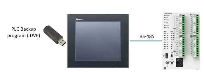
The current floor number is displayed at the top of the Cabin frame.įigure 1 displays the image we need to design which simulates the traveling direction and speed of the Cabin.In Local mode: we can control all previous functions by just touching the corresponding push-button images located at the bottom section of the HMI screen.There is an Image LED at the bottom and rightmost section of the HMI screen, which can be turned on/off via an input signal.The angular speed of rotation of the Cabin is also indicated by two flashing letters “Fast” or “Slow” in red color. Two green and red “arrow” images start flashing when the Hand indicator is rotating clockwise (CW) or counterclockwise (CCW) respectively to indicate the direction of an imaginary cabin when it is traveling up or down respectively.When the Cabin door is closed or opened, output signals D_closed or D_opend become High or Low respectively, and remain at that voltage level as long as the current status of the Cabin door is not changed.I call this output signal 1 st Floor Pulse or 1FP for short. PLC simulator generates an output signal which stays “1” as long as the Hand indicator is pointing at Floor # 1 and becomes “0” as soon as the Hand indicator moves away from this position.I call this pulse “ Every Floor pulse” or EFP” for short. The period of the mentioned pulse is about 0.5 seconds. PLC Simulator generates a pulse signal that goes through two signal transitions: from 0 to 1 and then returns from 1 to 0 anytime the Hand indicator reaches from any previous floor number to the next.The cabin light can be turned on/off via an input signal when the related signal is activated.The angular rotation of the Hand indicator to rotate either Fast or Slow AND Clockwise or Counterclockwise. In Remote mode: we can control the movement of the Cabin door to be closed or opened by two applied input signals. The control system has two modes of operation: 1- Remote 2- Local. In this project, we want to develop hardware/software to implement a 16 Floor Elevator simulator system based on a DELTA PLC and a WEINVIEW HMI device. To read more about that, click hereĪnd, to view the microcontroller based project in action, click h ere This is an upgraded version of the Elevator simulator project that was implemented a while ago. Posted Augby plcgoods in PLC based Projects, Tutorials 2152 0


 0 kommentar(er)
